Lesson Objective
- Understand logical and arithmetic shifts.
- Understand Bitwise manipulation and masks.
- Be able to extract, clear, set and toggle subsets of bits by using the AND, OR and XOR.
KS3, GCSE, A-Level Computing Resources
An advantage of Assembly Language. Bits can be manipulated in two ways:
Left Shift = Multiply. Each shift is the number multiplied by a power of 2
| 0 Shift | 0 | 0 | 0 | 0 | 1 | 0 | 0 | 0 | Original |
| 1 Shift | 0 | 0 | 0 | 1 | 0 | 0 | 0 | 0 | *2 |
| 2 Shift | 0 | 0 | 1 | 0 | 0 | 0 | 0 | 0 | *4 |
| 3 Shift | 0 | 1 | 0 | 0 | 0 | 0 | 0 | 0 | *8 |
Right Shift = Divide. Each shift is the number division by a power of 2
| 0 Shift | 0 | 0 | 0 | 1 | 0 | 0 | 0 | 0 | Original |
| 1 Shift | 0 | 0 | 0 | 0 | 1 | 0 | 0 | 0 | /2 |
| 2 Shift | 0 | 0 | 0 | 0 | 0 | 1 | 0 | 0 | /4 |
| 3 Shift | 0 | 0 | 0 | 0 | 0 | 0 | 1 | 0 | /8 |
When a binary number is shifted right logically, the least significant bit (LSB) is discarded and a 0 is shifted in to its place. The carry bit is set to the value of the LSB that was discarded.
| 1 | 1 | 1 | 1 | 0 | 1 | 0 | 0 | Carry Bit | ||
| 0 | 1 | 1 | 1 | 1 | 0 | 1 | 0 | 0 | Carry Bit |
When a binary number is shifted left logically, the most significant bit (MSB) is discarded and a 0 is shifted in to its place. The carry bit is set to the value of the MSB that was discarded.
| Carry Bit | 1 | 1 | 1 | 1 | 0 | 1 | 0 | 0 | ||
| Carry Bit | 1 | 1 | 1 | 1 | 0 | 1 | 0 | 0 | 0 |
Note: Logical shifts won’t work with a two’s complement negative number. Logical shifts only work with Unsigned Binary.
A Logical Shift applies to both left and right shifts. In a left shift, bits are moved left, and the vacated least significant bit (LSB) is filled with a zero. In a right shift, bits are moved right, and the vacated MSB is also filled with a zero. Logical shifts treat the binary number as a sequence of bits without considering its signedness.
Arithmetic Shifts only applies to right shifts. Similar to a left logical shift, bits are moved right. However, the vacated MSB is filled with a copy of the original MSB (sign bit). This preserves the sign of the number during the shift. Arithmetic shifts are crucial for signed number operations, especially when dealing with negative numbers in two's complement representation.
| 1 | 1 | 1 | 1 | 0 | 1 | 0 | 0 | Carry Bit | ||
| 1 | 1 | 1 | 1 | 1 | 0 | 1 | 0 | 0 | Carry Bit |
Overflow occurs when the result of a calculation is too large to be held in the number of bits allocated.
For example, adding two integers in an 8-bit byte (ignore the sign bit).
| 1 | 1 | 1 | |||||||
| 1 | 0 | 0 | 0 | 0 | 0 | 0 | 1 | 129 | |
| + | 1 | 0 | 0 | 0 | 0 | 0 | 1 | 1 | 131 |
| 1 | 0 | 0 | 0 | 0 | 0 | 1 | 0 | 0 | 260 |
Underflow occurs when a number is too small to be represented in the number of bits allocated.
It may occur if a very small number is divided by a number greater than 1.
Example: Shows a 8 bit binary number shifting one space to the right.
| 1 | 0 | 0 | 0 | 0 | 0 | 0 | 1 | ||
| ÷2 | 0 | 1 | 0 | 0 | 0 | 0 | 0 | 0 | 1 |
Boolean Logic:
Electronic circuits that perform Binary functions are called logic gates. Logic Gates form the basis of all logic circuits.
Logic Gates represent Boolean Equations. Each Boolean function is represented by a different symbol.
A truth table shows the results of Boolean equation from all possible combinations of inputs. They are used to show all possible outcomes from Boolean equations and logic gate diagrams. The truth table and logic gate symbol for show on the right of the screen. Or below on mobile browsers.
For an AND Gate the output is TRUE only if ALL inputs are TRUE.
Boolean Algebra Notation:
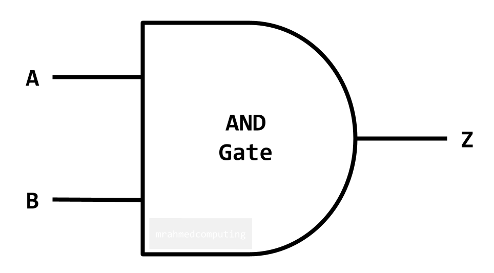
| A | B | Z |
|---|---|---|
| 0 | 0 | 0 |
| 0 | 1 | 0 |
| 1 | 0 | 0 |
| 1 | 1 | 1 |
For an OR Gate the output is TRUE if EITHER/ALL inputs are TRUE.
Boolean Algebra Notation:

| A | B | Z |
|---|---|---|
| 0 | 0 | 0 |
| 0 | 1 | 1 |
| 1 | 0 | 1 |
| 1 | 1 | 1 |
For a NOT Gate the output is the OPPOSITE (inverse) of the input.
Boolean Algebra Notation:
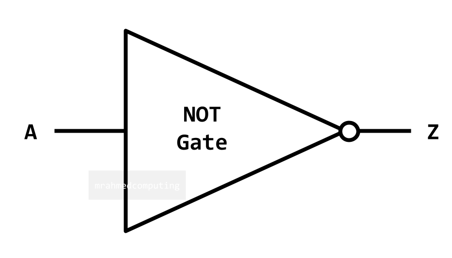
| A | Z |
|---|---|
| 0 | 1 |
| 1 | 0 |
For an XOR Gate the output is TRUE if only ONE input is TRUE.
Boolean Algebra Notation:
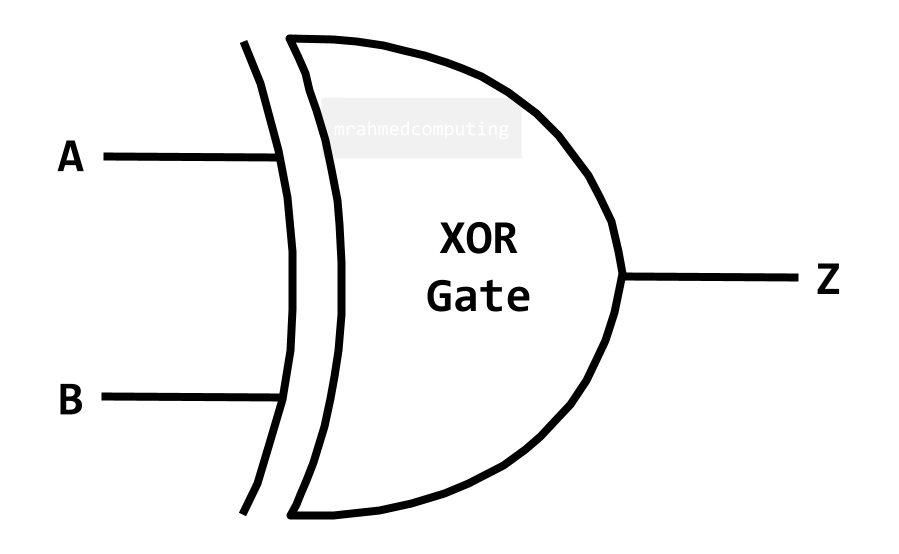
| A | B | Z |
|---|---|---|
| 0 | 0 | 0 |
| 0 | 1 | 1 |
| 1 | 0 | 1 |
| 1 | 1 | 0 |
The instructions AND, OR and XOR can be summarised in the table below:
| AND | OR | XOR | |
|---|---|---|---|
| Input A | 1010 | 1110 | 1001 |
| Input B | 1100 | 1100 | 1100 |
| Result | 1000 | 1110 | 0101 |
Input B is a mask, which in combination with the Boolean operator, will set, clear or toggle the input bits. Masking allows you to isolate, extract and edit a sequence of bits.
The AND operator can be used to clear a particular set of bits, leaving the other bits unchanged.
To clear the rightmost 4 bits. We would use the Mask (11110000) with the AND operator.
| Input A | 0 | 1 | 1 | 1 | 0 | 1 | 0 | 0 |
| Input B (Mask) | 1 | 1 | 1 | 1 | 0 | 0 | 0 | 0 |
| Output | 0 | 1 | 1 | 1 | 0 | 0 | 0 | 0 |
The OR operator may be used to set a particular bit, leaving the other bits unchanged. To set the bit 1, 4 and 8 (furthest left bit is bit 1). We would use the Mask (10010001) with the OR operator.
| Input A | 0 | 1 | 1 | 1 | 0 | 1 | 0 | 0 |
| Input B (Mask) | 1 | 0 | 0 | 1 | 0 | 0 | 0 | 1 |
| Output | 1 | 1 | 1 | 1 | 0 | 1 | 0 | 1 |
The XOR operator can be used to toggle a particular bit, leaving the other bits unchanged. To toggle the rightmost 4 bits. Leaving the leftmost 4 bits unchanged. We would use the Mask (00001111) with the XOR operator.
| Input A | 0 | 1 | 1 | 1 | 0 | 1 | 0 | 0 |
| Input B (Mask) | 0 | 0 | 0 | 0 | 1 | 1 | 1 | 1 |
| Output | 0 | 1 | 1 | 1 | 1 | 0 | 1 | 1 |
Routing traffic on a network
How do I work out the Subnet Mask?
135.68.1.1/16
Note: /16 would specify the network part. This mean the subnet mask would be a binary IP address made up of 16 leading 1’s.
| IP Address: 135.68.1.1/16 | ||||||||||||||||||||||||||||||||||
| 1 | 0 | 0 | 0 | 0 | 1 | 1 | 1 | . | 0 | 1 | 0 | 0 | 0 | 1 | 0 | 0 | . | 0 | 0 | 0 | 0 | 0 | 0 | 0 | 1 | . | 0 | 0 | 0 | 0 | 0 | 0 | 0 | 1 |
| Subnet Mask: 255.255.0.0 | ||||||||||||||||||||||||||||||||||
| 1 | 1 | 1 | 1 | 1 | 1 | 1 | 1 | . | 1 | 1 | 1 | 1 | 1 | 1 | 1 | 1 | . | 0 | 0 | 0 | 0 | 0 | 0 | 0 | 0 | . | 0 | 0 | 0 | 0 | 0 | 0 | 0 | 0 |